
Fibre Channel hardware interconnects storage devices with servers and forms the Fibre Channel fabric. The fabric consists of the physical layer, interconnect devices, and translation devices. The physical layer consists of copper and fiber-optic cables that carry Fibre Channel signals between transceiver pairs. Interconnect devices, such as hubs, switches, and directors, route Fibre Channel frames at gigabit rates. Translation devices, such as Host Bus Adapters (HBA), routers, adapters, gateways, and bridges, are the intermediaries between Fibre Channel protocols and upper layer protocols such as SCSI, FCP, FICON, Ethernet, ATM, and SONET. Storage devices at one end of the fabric store trillions of bits of data while servers on the other end distribute the data to hungry users. Fibre Channel hardware stores and distributes data across the work group and the enterprise.
Physical Layer
Media
The Fibre Channel fabric is connected at the physical layer by fibre, a term coined by the Fibre Channel industry to mean optical fiber and copper wires. The physical layer and transceivers use the same cable infrastructure that is used in other networks such as LANs and telecommunications. Thus, cables can be installed once and used for any of these networks.The distance over which a Fibre Channel link operates depends on the type of media used and what transceivers are attached to the media. Each physical medium uses a transceiver that has been optimized for that medium.
Speed
The operating speeds of Fibre Channel are outlined in Table 1.
Table 1. Fibre Channel Link Speeds
| Speed | Throughput (MBps)* | Line Rate (Gbaud) |
Release Date (Year) |
| 1 GFC | 200 | 1.0625 | 1998 |
| 2 GFC | 400 | 2.125 | 2000 |
| 4 GFC** | 800 | 4.25 | 2002 |
| 10 GFC | 2400 | 10.5 or 3.1875 | 2002 |
* Throughput for duplex connections
** Intrabox applications
Table 1: Although Fibre Channel links already operate at over 1 Gbps, many applications require higher speeds for better performance. 2 GFC became available in disk drives and HBAs in late 1999, and will become available in interconnect devices in 2001. 10 GFC will keep pace with other networking technologies that are converging at 10 Gbps.Interconnect Devices
Fibre Channel interconnect devices consist of hubs, switching hubs, switches, and directors, as shown in Figure16.
Translation Devices
Translation devices connect the Fibre Channel network to outside networks or devices as shown in Figure7. The most common translation device is the HBA or Fibre Channel Adapter. An HBA connects the Fibre Channel network to the server’s host bus, which can be PCI or SBus. A bridge connects legacy SCSI or ESCON storage devices to the Fibre Channel network. An adapter connects FC to IP networks such as Ethernet or Token Ring. A gateway (sometimes referred to as a router or director) interfaces to telecom networks, such as ATM or SONET. Multi-function routers connect multiple Fibre Channel ports to multiple protocols such as SCSI, ATM, or Ethernet.
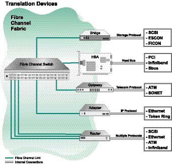
Figure 7: Translation devices interface between the Fibre Channel fabric and other networks.
Storage Devices Storage takes many forms and comes in a variety of configurations, such as disk drives, JBODs, RAIDs, storage subsystems, tape drives and tape libraries, as seen in Figure18 and 19. These storage devices store gigabytes in a single disk drive, terabytes in a storage subsystem, and petabytes in a tape library.
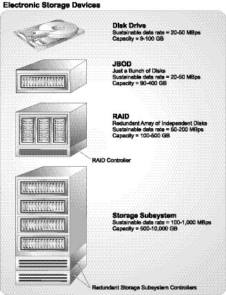
Figure 8: Electronic storage devices are based on the 3.5 disk drive. Disks can be grouped to form JBODs and expanded to RAIDs with a controller. Storage subsystems combine advanced software with redundancy to provide incredible performance gains over previous storage devices.
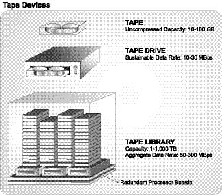
Figure 9: Tape devices scale from a single drive to fully automated, robotic tape libraries. Tape drives are designed for archival purposes and scale to colossal proportions with multiple tape silos. A single tape drive can back up a stand-alone computer or a network of computers. Tape libraries can back up corporate data for decades.
Servers
The server is the initiator in the Fibre Channel SAN and is the interface to IP networks. Servers interact with the Fibre Channel fabric through the HBA, as seen in Figure20. Microprocessors utilize single I/O buses or multiple host I/O buses to eliminate single points of failure. Servers can have multiple microprocessors and host I/O buses to implement several instances of the operating system concurrently. Some high-end servers utilize over 50 microprocessors and have over 10 instances of operating systems.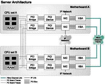
Figure 10: High-end servers use duplicate host buses, HBAs, NICs, and processors to enable high throughput and reliable computing. Advanced servers incorporate multiple host I/O buses and processors to allow multiple instances of operating systems to run simultaneously.
Reliability, Availability, and Serviceability (RAS) is a common industry term that correlates to the downtime of the system. Reliability measures unplanned downtime and is usually measured as Mean Time Between Failures (MTBF). Reliability usually decreases with multiple moving parts, complex mechanics and increased temperatures. Availability describes the planned downtime and can be expressed as the percentage of uptime. Availability can be limited by single points of failure, code upgrades, or other routine servicing that makes a device unavailable. Serviceability measures the time to repair a failure and has the metric of Mean Time To Repair (MTTR). Complex repairs and limited replacement parts can increase serviceability. Requirements for high availability applications can be specified by these three components of uptime.